— DCS and AUTOMATION
The Automation and Control System is based on SIEMENS PLC 1500 series and the CPU can be placed in every MCC equipment selected.
Two PC are connected into a common platform. This allows to control and set the system wherever hardware selected. The machines, configured as REDUDANT SERVER ensures to not lose any data in case of crashes.
The FULL TAGS System is expandable adding simple components like ethernet or serial hubs to the existing PC.
Therefore, the System can be considered a real DCS , where Level 1 managements are possible – production statistics, consumptions, certificate emissions, etc.)

Typical Layout of an expandable DCS System Automation
— SUPERVISOR and SCALINK ® PRODUCT FEATURES
SCALINK ®: Data multiple source
The flexible structure allows to enable any module based on the automation and communication: All the modules are licensed and available.
The most used are:
- OPC server/client;
- Modbus RTU master/slave o TCP client/server;
- Siemens S7 via MPI o TCP;
- ABB Infi90 via SCSI o seriale;
- Siemens S5…
In case of new data source needed, a new module can be activated without added costs or the existing license modification.
SCALINK ®: Scalability
The typical architecture is based on a multi-operator platform; two of them are named I/O Server – with independent configuration or backup one of the other – and acquire the data from the system automation they locally process. The remaining operator points are Clients, and they get the I/O server data having a remote control. A new Client add can be done later on, in case.
SCALINK ®: Other features
- Maximum signal acquirement limited by the hardware, only (up to 100.000 signals);
- Signal menu readable via OpenOffice, Calc, MS Access, Borland DB, or SCALINK itself;
- Recipes management:
- Multi-level user management;
- Reports upon fixed parameters (date, hour, event … either text or graphs);
- Multi languages support. Txt Translation made by external tools;
- On-line pages printouts in different extensions (Bmp; Jpg; WinMetafile);
- Present Alarms ISA1 on screen and/or printer;
- Historical Alarms on permanent file (up to 20.000 records per day);
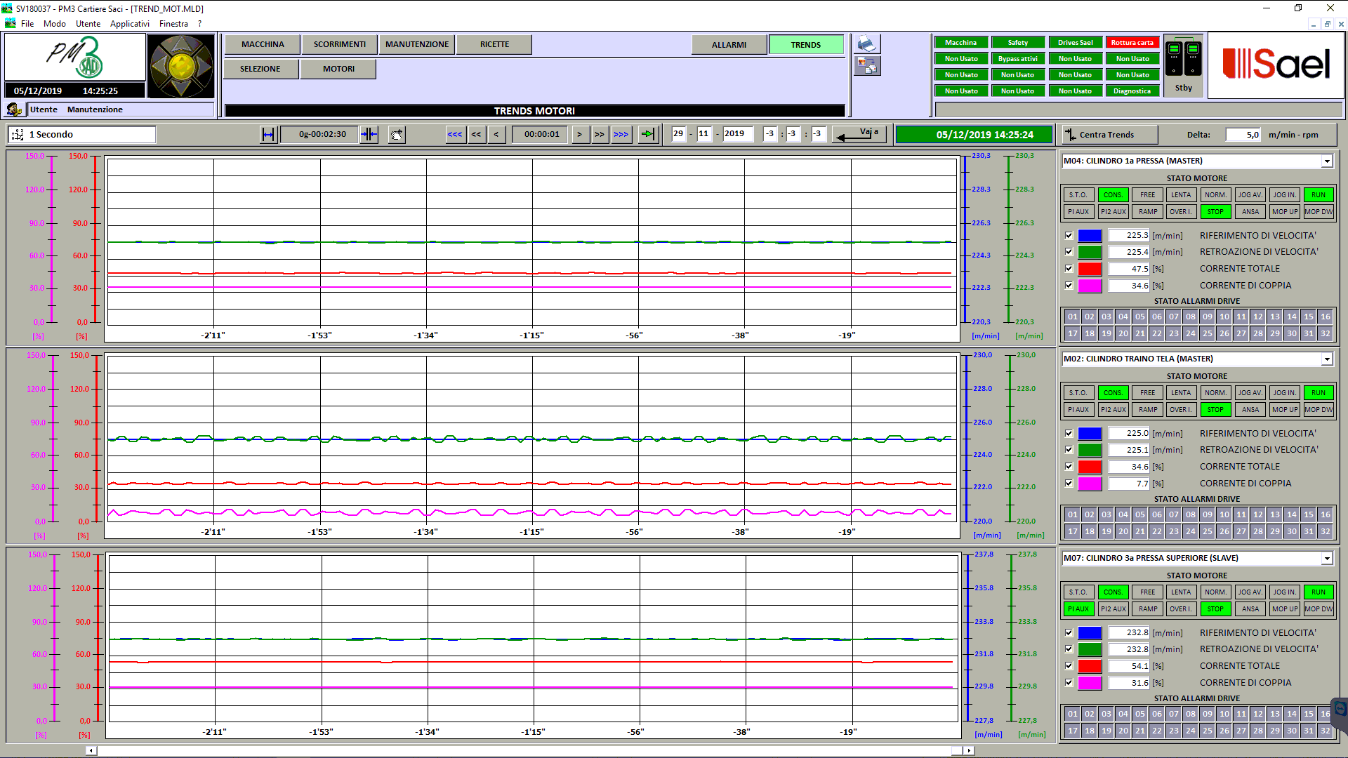
- Data storage and their visualization on curves;
- Plant snapshot (hours, Events, pics);
- Data Base Run Time values free accessible from external sources/programs like OPC Server, OPC UA, Modbus RTU, Modbus TCP, DDE Server, API, etc …

Client/Server Architecture (example)

SCALINK ®: Performances and features
“Alarm Help”. For each alarm there is a data storage – txt file directly edited by the operator -. By this record every operator can provide and transfer any information referred to the tests an d activities.

Although, it is possible to link every single alarm to the specific electrical diagram of the cabinet .
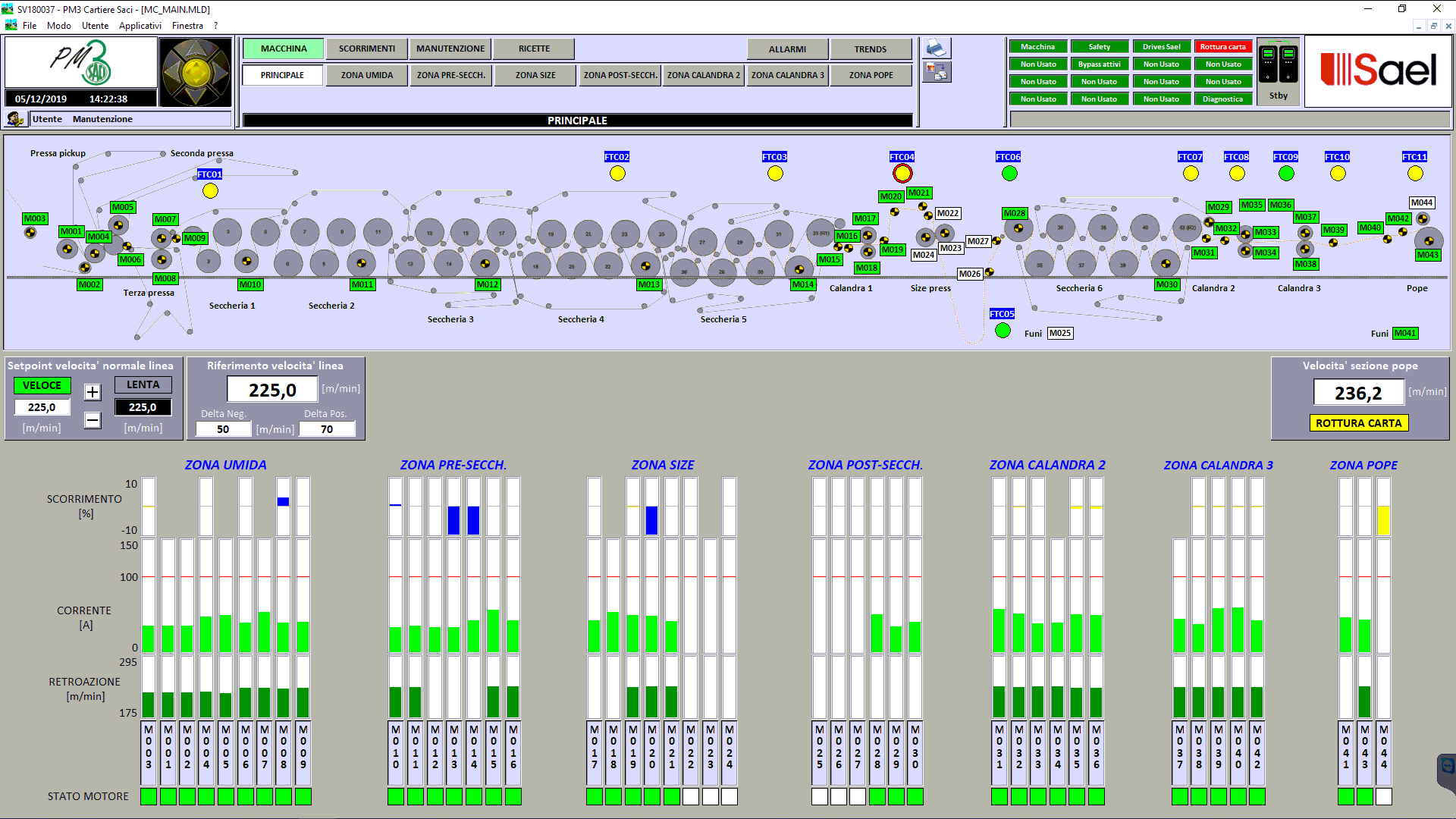
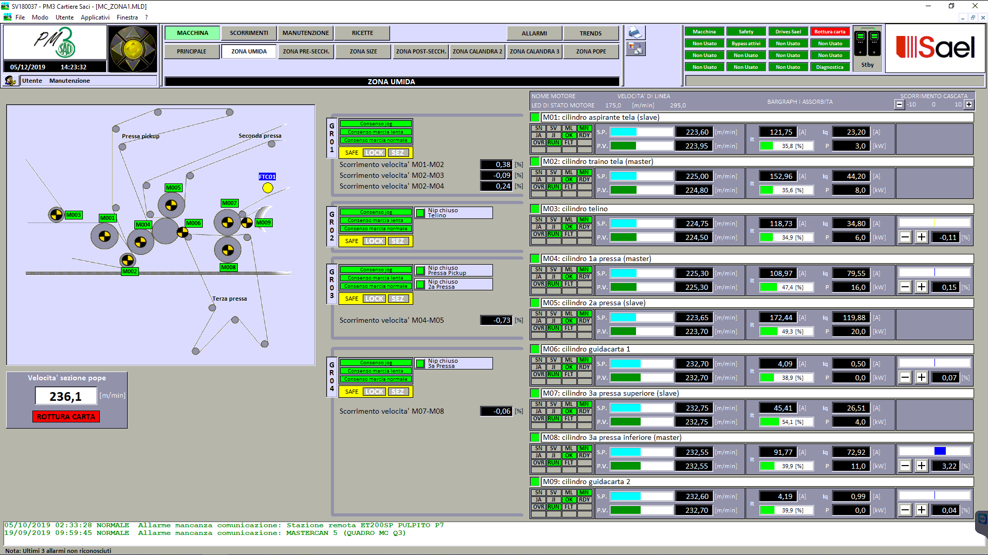
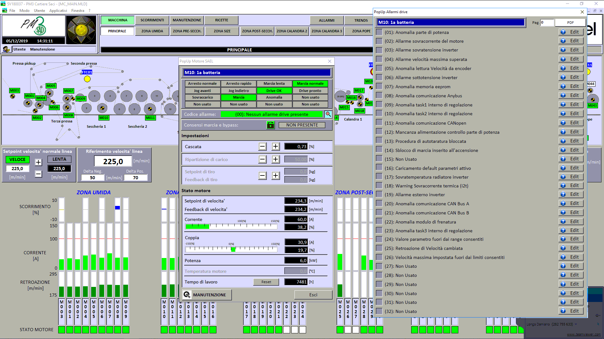
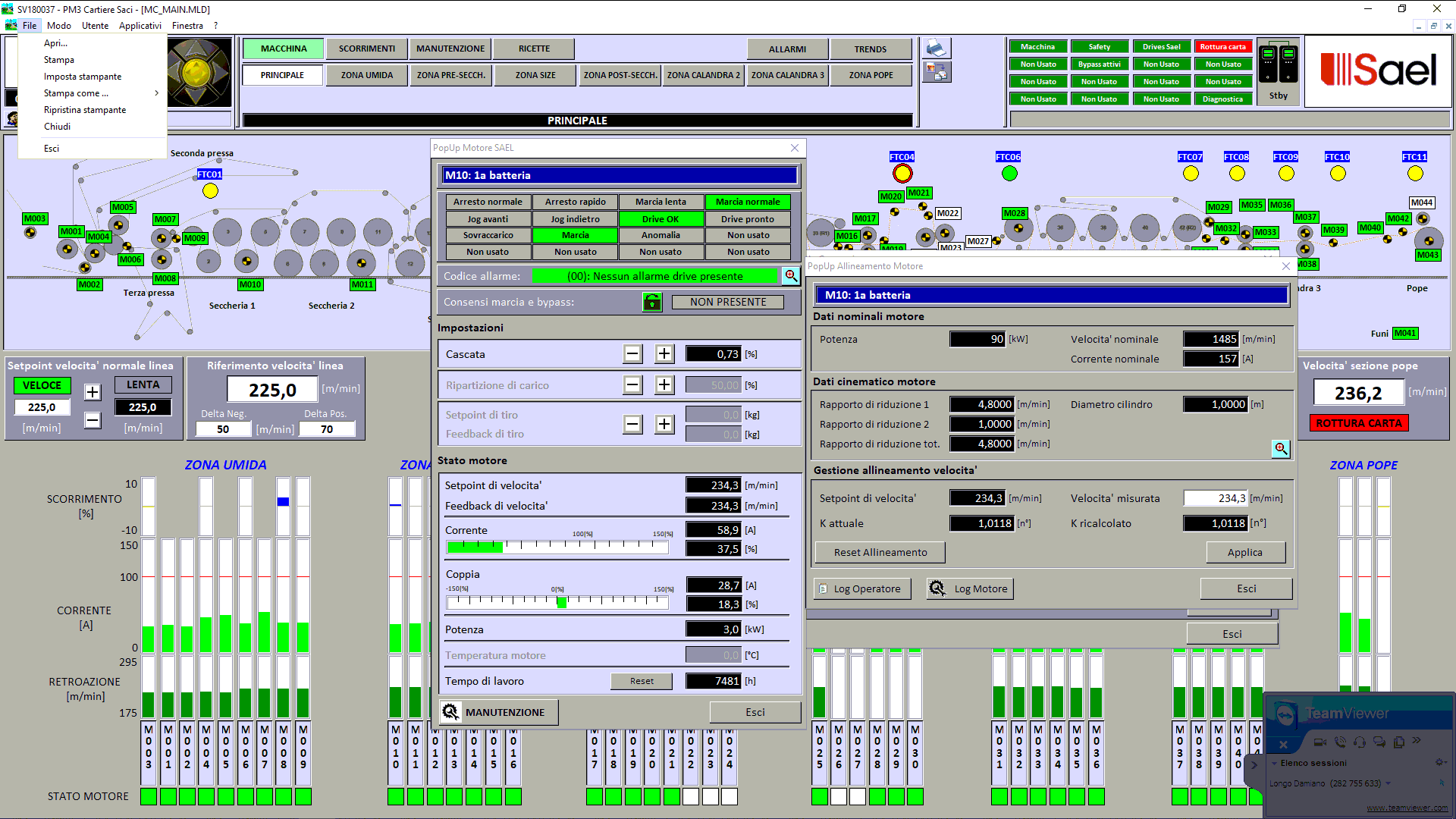
SCALINK ®: How to control the utilities via supervisor
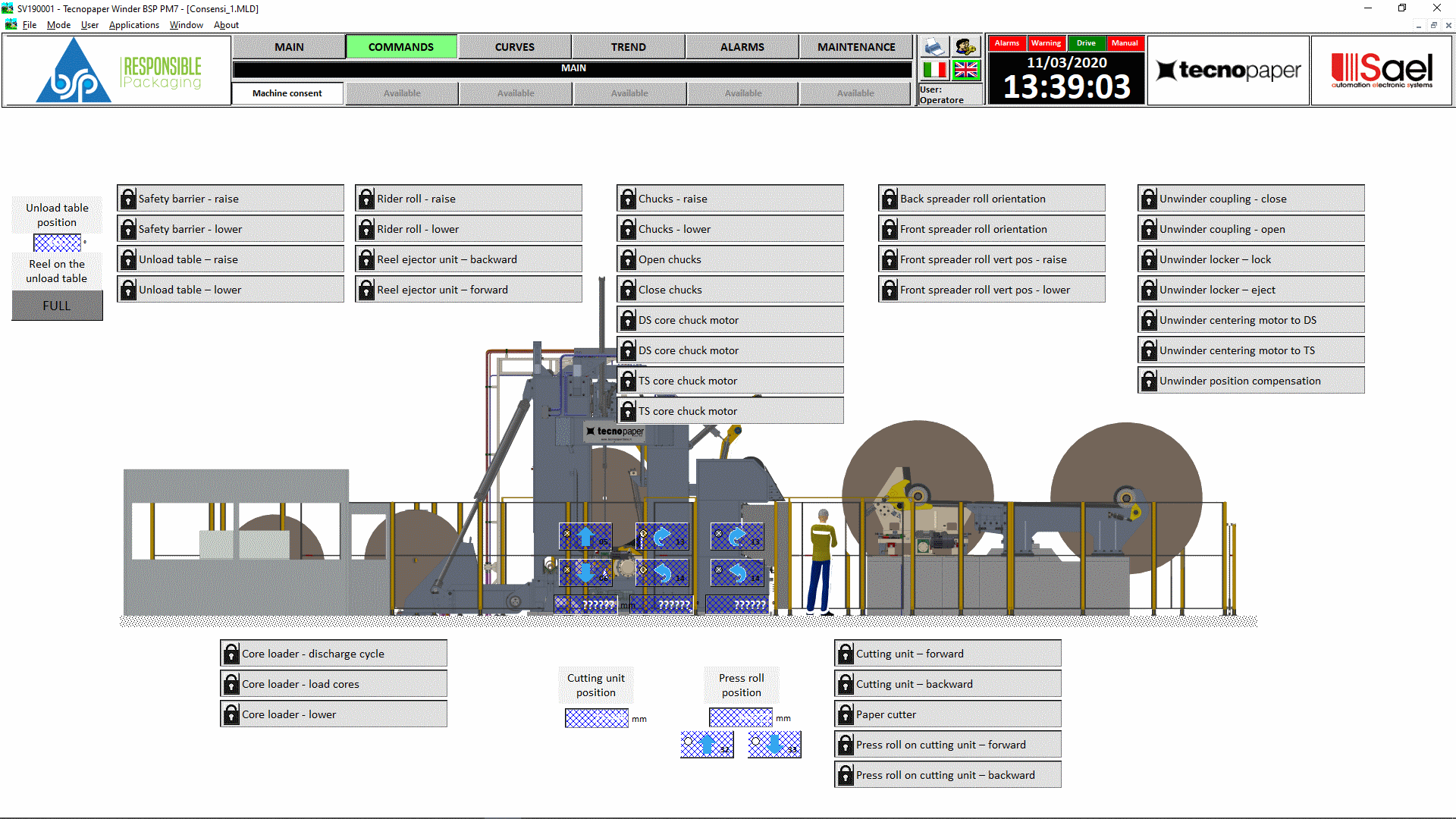
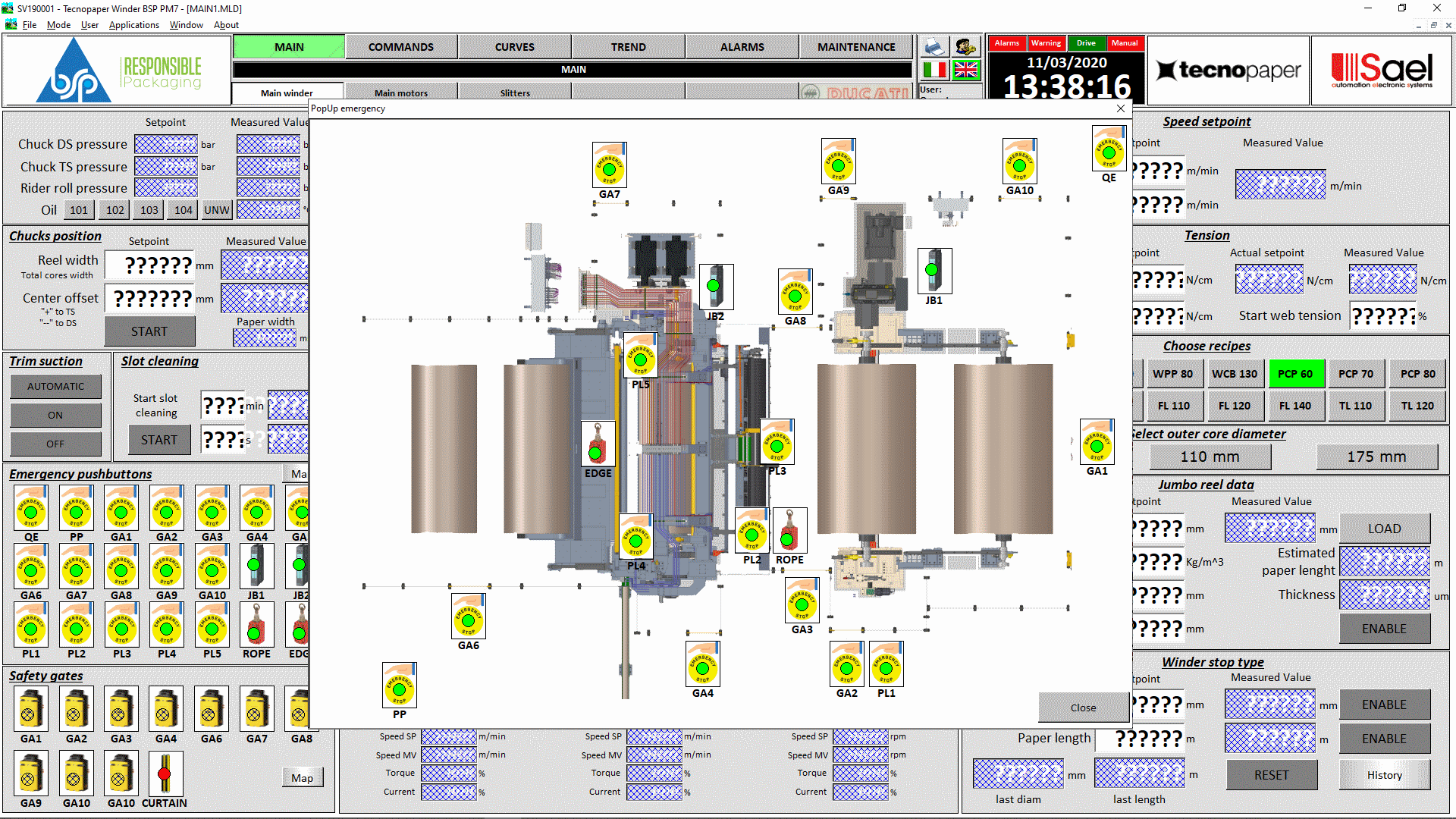
Every Valve, motor, regulation loop can be controlled via supervisor. After being in the related page, point the arrow to the utility desired and set. A left-click of the mouse Pops up the utility. Following some examples:


Motor
Valve ON/OFF

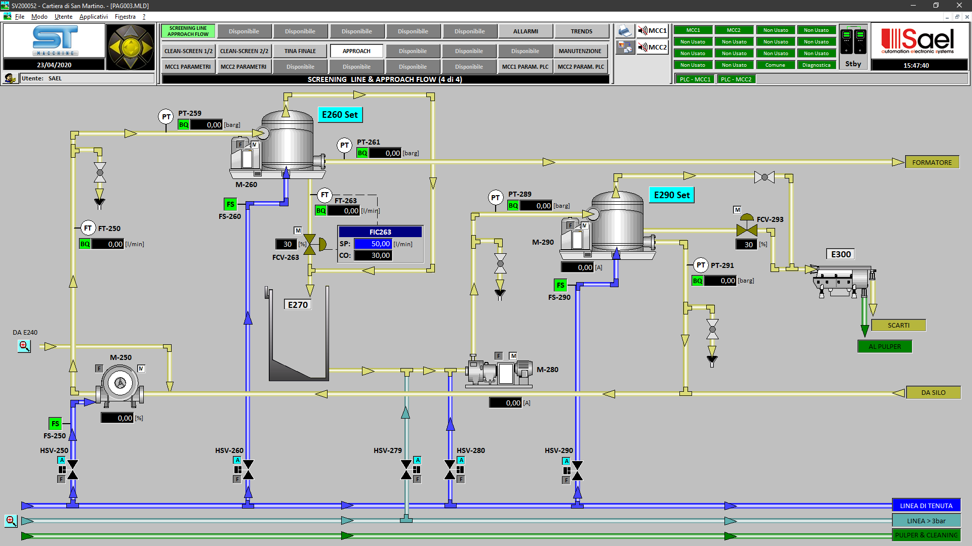
Regulation Valve / Managing Station (PID)
Every regulation Pop-up, apart the logical states themselves, there is a Trend with SP/PV/CO parameters, as well its direct controls, having a quick adaptation.


— Software Automation System Configuration
The control logics are implemented upon demand.
All the sequences, regulation algorithms and data exchanging are managed by the CPU. The main utilities are:
Electro valves ON-OFF
All the electro valves are integrated into the automatic sequences whenever required. They have a manual control system in the page of the specific supervisor.
For each electro valve are managed the linked control sensors, as well as the opening/closing times. The status is displayed in real time.
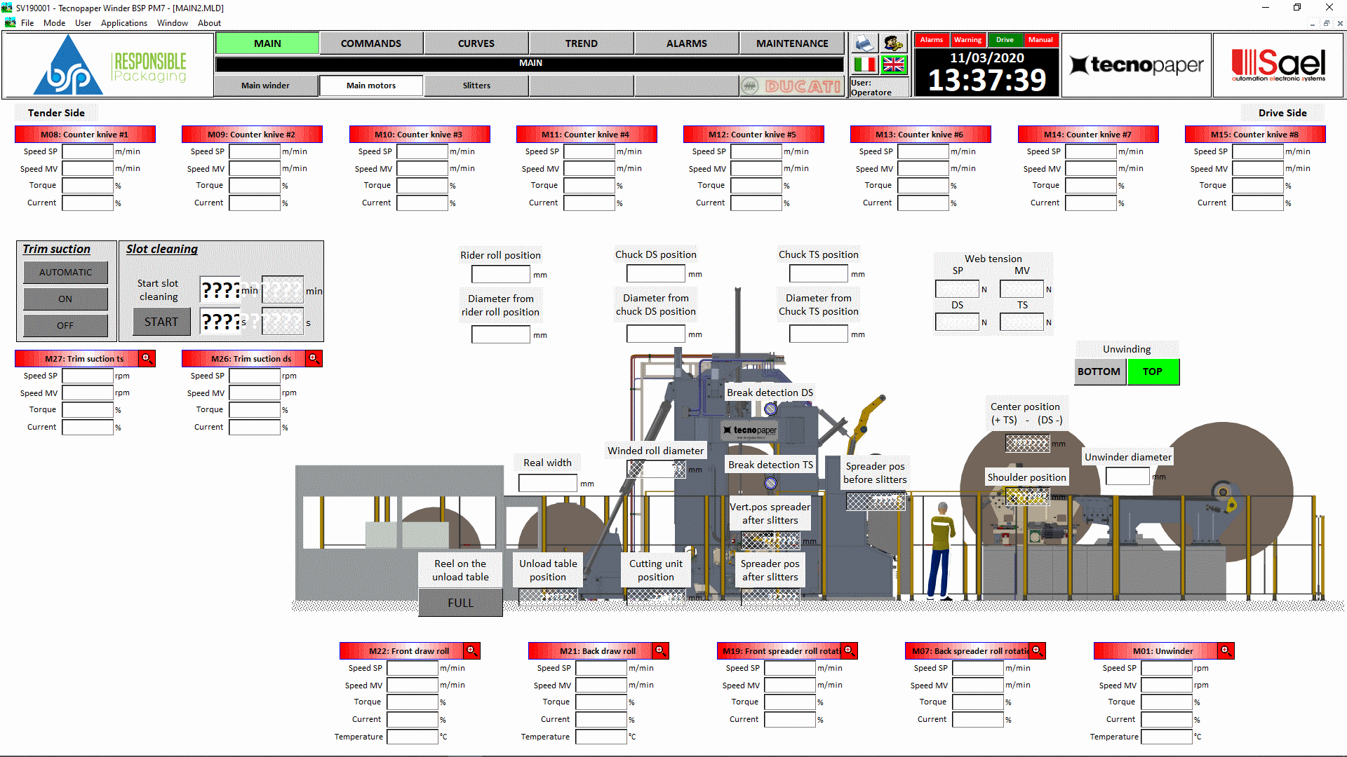
Motors
All the motors are integrated into the automatic sequences – whenever required – . They have a manual command in the specific page of the supervisor.
Every motor has an interface with the MCC: Run, Fault, Status and Current.
For each motor there is a starting time management, as well as the alarm status.
Regulation loop
Every regulation loop has a graphical interface in the supervisor.
The operator interface permits to set the PID function (AUTO or MANUAL). In case of AUTO, the machine will calculate the parameters. In case of MANUAL the operation is made by the personnel. The PID, KP, KI, KD constants are settled in the control logics


Are you interested in learning more?
Contact us by filling out the form